Patient-specific implants · printed titanium
The cranial or maxillofacial implant designed for a single patient.
IME TECH carries out the medical study, the design and the metal additive manufacturing of your patient-specific implants, from the CT scan, working directly with the surgeon.
- 01
- Medical study
- 02
- CAD design
- 03
- Metal manufacturing
Cranioplasty · 3D model
Our work
Five implants, five patients.
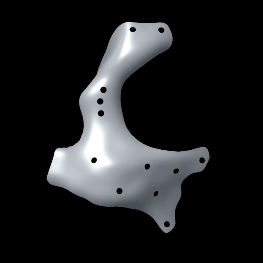
Each part below was designed and manufactured for a real case. It can be explored in 3D, to scale, and placed on a table in augmented reality.
One team
From the CT image to the implant delivered to theatre, with no subcontracting between steps.
The engineers who study the case are the ones who design the implant and follow its manufacture. The surgeon keeps a single point of contact, and every design decision remains traceable to the final part.
- 01
Medical study
Imaging review, defect analysis and reconstruction strategy defined with the surgeon.
- 02
Design
Implant designed on the patient’s anatomy, with a placement plan and cutting guides when needed.
- 03
Manufacturing
Laser powder-bed fusion printing, post-processing and inspection in our workshop.
Solutions
Three fields.
Every implant is unique: shape, thickness and fixation are defined from the patient’s anatomy.
A — Neurosurgery
Cranioplasty
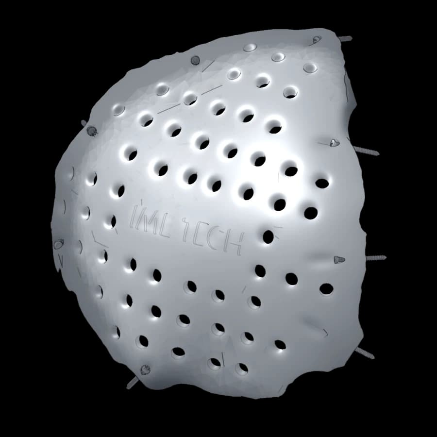
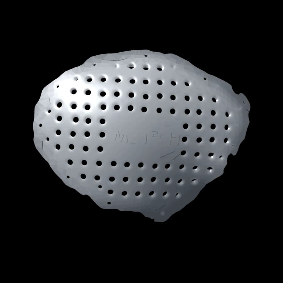
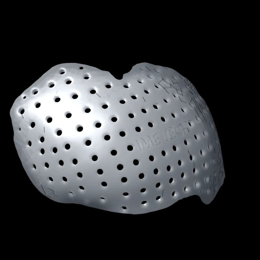
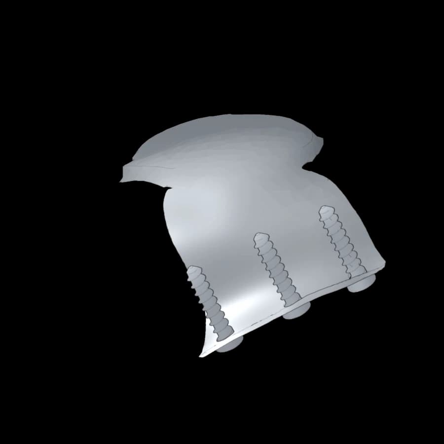
Titanium cranial implants that follow the curvature of the patient’s vault and are fixed around the edge of the defect. The plate below describes a real case: geometry, fixation and cross-section profile, with values measured on the manufacturing files.
Explore the case in 3DIndications
- Defect after decompressive craniectomy
- Reconstruction after tumour resection
- Sequelae of head trauma
- Revision of a previous cranioplasty
13/4 view · implant in place
2Lateral view · envelope
3Section A-A · profile and fixation
4Measured characteristics
- Overall size
- 107 × 107 × 32 mm
- principal axes
- Thickness
- 2.9 mm
- median · 2.1–3 mm (interquartile)
- Outer surface
- 96.2 cm²
- Volume · mass
- 28.3 cm³ · ≈ 125 g
- Ti-6Al-4V, 4.43 g/cm³
- Perforations
- 52 × Ø 3.6 mm
- Bone support
- ≈ 470 mm²
- inner face within 1 mm of bone
- Fixation
- 8 screws Ø 1.5 × 15 mm
- head Ø 2.5 mm
- Screw in bone
- ≈ 8.6 mm
- measured on section A-A
B — Maxillofacial surgery
Maxillofacial reconstruction
Implants, plates and cutting guides designed on the surgical plan: resection and reconstruction are prepared together, before surgery.
Indications
- Segmental mandibular reconstruction
- Orbital floor and walls
- Malar bone and zygomatic arch
- Patient-specific reconstruction plates and cutting guides
C — Ophthalmology · oculoplastic surgery
Orbital reconstruction
Thin implants that rebuild the orbital walls in contact with the orbital contents. Fixation is moved to the rim, away from fragile structures, and the axis of every screw is set at planning.
Indications
- Orbital roof and walls: fractures, bone loss
- Reconstruction after orbital tumour excision
- Correction of enophthalmos and orbital volume
- Orbital rims and patient-specific fixation
Process
Six steps, with surgical approval before anything is manufactured.
The surgeon takes part in planning and approves the design. Nothing is printed without their written approval. The animation follows a real cranioplasty case, from the scan to implantation.
Step 01 / 06
Imaging received
01 / Surgeon → IME TECH
Imaging received
The surgeon sends the patient’s CT scan in DICOM format. We check slice quality before starting the study.
- Thin-slice CT scan
- DICOM upload from the form
- Clinical context and indication
02 / Engineers + surgeon
Medical study and planning
Bone segmentation, defect analysis and choice of reconstruction strategy, discussed with the surgeon in an online planning session.
- 3D segmentation
- Symmetry analysis
- Choice of fixation zones
03 / IME TECH design office
CAD design of the implant
The implant is designed on the patient’s morphology: thickness, perforations, lattice structures and screw holes. The design is submitted to the surgeon for approval.
- 3D model and placement plan
- Cutting guides if needed
- Written approval by the surgeon
04 / IME TECH workshop
Metal additive manufacturing
The implant is printed layer by layer by laser fusion of a titanium powder bed, with traceability of the powder batch and machine parameters.
- Ti-6Al-4V ELI powder
- Laser fusion (L-PBF)
- Batch traceability
05 / Quality control
Post-processing and inspection
Heat treatment, support removal, surface finishing, then dimensional inspection against the approved model.
- Heat treatment
- Finishing and cleaning
- Dimensional inspection
06 / IME TECH → hospital
Delivery to theatre
The implant is delivered with its manufacturing file and, on request, an anatomical model for rehearsing the procedure.
- Manufacturing file
- Optional anatomical model
- Post-operative follow-up
Material
Ti-6Al-4V ELI titanium, laser-printed.
The reference alloy for craniomaxillofacial implants: light, strong, biocompatible and corrosion-resistant.
Additive manufacturing does what machining cannot: internal lattice structures, distributed perforations and shapes taken directly from the anatomy, with no tooling or mould.
| Alloy | Ti-6Al-4V ELI (grade 23) |
|---|---|
| Reference material standard | ASTM F3001 |
| Process | Laser powder-bed fusion (L-PBF) |
| Density | 4.43 g/cm³ |
| Elastic modulus (bulk) | ≈ 110 GPa |
| Layer thickness | 30 – 60 µm (typical) |
| Structures | Solid, perforated or lattice |
Typical values for the alloy. The characteristics of each batch are recorded in the manufacturing file.
Fitted to the patient’s bone contour
The implant is modelled on the CT segmentation: less intraoperative shaping than with a stock plate, and symmetry controlled from the planning stage.
Shared planning
An online session with the engineer: you steer the choices, we turn them into geometry.
Cutting guides and models
Resection guides and anatomical models to reproduce the planned procedure in theatre.
One lead engineer per case
The same contact follows the case from receipt of the imaging to delivery, and remains available after surgery.
Resources
Information suited to each reader.
A recent CT scan of the area in DICOM format, ideally with thin slices and no gantry tilt, together with a short description of the indication and the intended date of surgery. You can attach the DICOM files directly to the request form.
Submit a case
Describe the case and we will come back to you with a feasibility study.
- 01You describe the case and attach the DICOM CT scan.
- 02We check the imaging and study feasibility.
- 03You receive the feasibility, the lead time and the planning date.
CENTRE D'IMAGERIE MEDICALE CLINIQUE AVICENNE57 Bis, Avenue Mohiédine Kelibi – Manar II, 2092 Tunis, Tunisia